Calculate Angle To Form Sheet Metal

Right angles are the most common feature found in most sheet metal fabrication.
Calculate angle to form sheet metal. Die edge radius in. Typical acute angle tooling profiles are 30 45 and 60 though there is custom tooling and air bending allows for the forming of any angle larger than the angle of the punch tip. The formula for calculating sheet metal bending allowance is please refer to the above picture. Work piece the general term for the sheet metal part being bent.
Tolerances general dimensioning and tolerances of bends and sheet metal. Sheet metal forming processes are those in which force is applied to a piece of sheet metal to modify its geometry rather than remove any material. You can calculate the punching tonnage been required with the help of the following punching force calculation formula blanking force formula. When designing parts for laser cutting one should not make holes smaller than the thickness of the material.
Cells on the right will output the desired values. Punch edge radius in. If you punch round holes or square holes or some other forms of holes through a given thickness of metal you just want to know the force required to punch a hole in steel. Straight angle a geometry term for an angle which is equal to 180.
By doing so the sheet can be bent or stretched into a variety of complex shapes. Continuing with the example introduced in figure 9 our required inside dimension is 0 250 in. With this free online tool we quickly get the sheet metal bend deduction and therefore the sheet metal blank initial flat length from the finished part measurements. Tooling general term for the dies punches and holders found on press brake equipment.
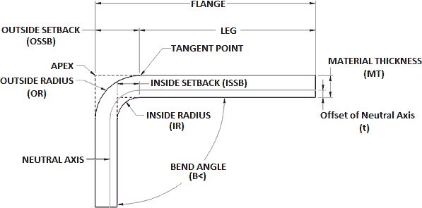
Ba bend angle π 180 r k factor t eqn 1. Punching force calculation formula. Bends in sheet metal are manufactured using sheet metal brakes. Sheet metal parts with a minimum of 0 9mm to 20mm in thickness can be manufactured.
Where ba is bend allowance. Ultimate tensile strength psi. The applied force stresses the metal beyond its yield strength causing the material to plastically deform but not to fail. You only have to insert interior angle flange lengths k factor inside radius and material thickness.
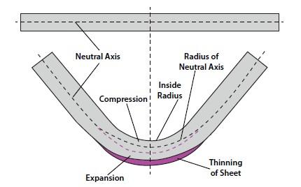
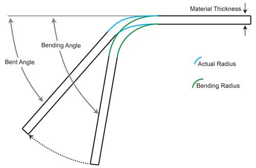
Od 90 complementary bend angle a dp b sine of bend angle 2 mt di b od 2 actual machine input depth dp di rp 0 03. A our angle is 45 degrees and our material thickness mt is 0 250 in. When the sheet metal is put through the process of bending the metal around the bend is deformed and stretched. A 1 degree tolerance on all bend angles.
R is inner bend radius. As this happens you gain a small amount of total length in your part.


